Friday, February 24, 2012

Tinman and Lemonhead

My son and I built a couple of those little fume extractors so we can stop breathing in so much solder fumes.

Of course, we used some candy tins for the cases. We used  a big Altoids tin for one, and a little novelty one I got from Target for the other one.


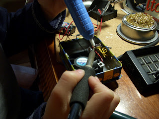
Here's William working on the second one. The first, in silver Altoids can, is already being used to keep the air clear.

Right now the front is just opened, but I've ordered a big sheet of filter material, which I will cut to fit each fume extractor.


To the right you can see a close up of the bigger extractor in action.


I used one of these old switches that I've had lying around forever. William is de-soldering the contacts with a solder pump, which he loves to do. The old solder was pretty stubborn, but we got the job done.

I love the little lemons on the sides of the box. Lemon-y, lemon-y, lemon-y!

Actually, now that I look at it, they look a little like Charlie Brown.


 Excellent results. Lemonhead!


Wednesday, February 22, 2012

Rotating LED Thingy

Idea and Design
My son William wanted to build an LED light chaser. So I hunted around for a circuit, and dug around in my spare parts.


I decided to build something based on this circuit.
The only differences are, I used a 4069 hex inverter instead of a 4049, because I have a bunch of them, and I changed out the 100 kohm resistor. I replaced the resistor with a 10 kohm fixed resistor in series with a 50 kohm potentiometer. That gave me a nice slow speed at one end and a very peppy speed at the other end.
BTW, the parts list for this project listed on the web page above specifies 150 ohm current limiting resistor, which is what I used, not the 470 ohm resistors shown in the schematic.  Also not clear on the schematic is that the ends of all those current limiting resistors need to to to ground.

The Gathering
As it happened, I had a circular prototyping board from Radio Shack. I did have to go out and buy a 4017, plus I picked up five pair of different color LEDs, and a bunch of 150 ohm resistors. Radio Shack didn't actually carry a 4017 chip, but they had their own LED chaser kit for sale that used the same chip. So I picked it up and stole the chip. I'll order a replacement and build the kit or give it to someone at some point. 
As I was laying out the circuit on a breadboard, I remembered I had the wooden base of a snow globe that had broken lying around. Then I found a plastic dome that almost fit. I would have to route the hole in the base a bit bigger. A toggle switch for power and a potentiometer and a few other parts and I was ready to go.

The Build
Here's the thingy all breadboarded out. I used a small multi-turn pot for the breadboard. It was replaced with a panel mount pot for the final build.
(click image for close-up of the breadboard)

As I mentioned, I had to route out the edge of the base to fit the dome. That was a bit tricky, but I managed fairly well and didn't even endanger myself. I can't recall what the dome was from. Some broken toy or something. It's fairly thick plastic, though. I'm glad I saved those two pieces, and that they found each other in this project.

The base also needed some other work. I drilled out holes for the power switch on one side and the potentiometer directly across. Some careful measuring and drilling were required. The sides of the base are pretty thick, so I had to countersink the mounting holes using Forstner bits.
Quick tip: When making countersunk holes for a switch or potentiometer or whatever, you need three sized bits. First a very small bit to drill a pilot hole. Next the largest bit to make room for the fastening nut on the outside. That cut doesn't pass all the way in, but stops at an appropriate depth. Lastly, a middle sized bit just slightly larger than the diameter of the mounting shaft is used to drill all the way through. With this method, you always have a small pilot hole to keep everything centered.
I mention this, because I forgot to do that when I drilled the holes for the power switch. So my last cut was a little rough without a proper pilot. Compare the cut for the power switch on the left, with the cut for the potentiometer on the right. You can also see some of my sloppy routing along the top of the left picture. It's not perfect, but it look OK.

Last cut on the base, I countersunk two more holes to hold the mounting screws.

I used brass tubing to make some standoffs, and some 6-32 threaded rod and brass nuts to mount the circuit board.

Despite the crazy nest of wires above and below the board, and the solder blob jungle underneath, the project came off rather well.

Here's the finished product. If you click on it you'll get a higher resolution view. I still need to find a nice knob for this project.  It looks very Victorian to me. I won't say it looks steampunk, because integrated circuits are really, really not steampunk.

Fish-Fillet

I present to you, one fish toy.


And now...

Remove the screws- except for the one that got stuck and wouldn't let go!


Gently pry open the two halves- except that the peg and socket holes at the front got stuck and finally broke!


And we have... fillet of fish!


The tail movement uses a simple gear motor and a cam.


I had to cut and pry through some glue before the motor case could be removed. It was pretty well sealed for water tightness, but that's not needed anymore.


I was hoping for more room inside the fish, so I could integrate the electronics for the Fish Tank. Unfortunately, it's too tight in there. We'll have to keep most of the electronics external.


More updates soon...


Thursday, February 16, 2012

Ideas swim like fish

I think the creative flow that an idea takes as it develops is interesting. Usually I'm not too aware of the process, but today I am looking back on an idea that developed in fits and starts.

Monday

It was about 1:00AM. This is when the idea started. I wouldn't have known it then. It is only clear looking back on it now. I couldn't sleep, so I went downstairs and started cleaning my work area a bit. That led to a surprise, which led to me writing this email to a friend.

Doug,

I was just cleaning up my work area (long overdue) and I came across the
box with your turtle bot all nicely packaged and ready to go. Opps!

I'm really sorry about that. I sort of lost track. At this point, I'm just feeling bad
to have forgotten your little robot and the Propeller Head Geek plaque you
sent for Maker Faire for so long.

I also realized I never wrote up a robot page or a review of the tank kit
you sent me, which I had always intended to do.

I'll send it to you.
Or words to that effect. I packed up Doug's stuff, but then...

Wednesday

I said to myself, I really should write that review of Doug's Little Tank kit. WAIT! I've got his other robot sitting right here, ready to ship back to him. I might as well review that one too.

So I unpacked it (again) and took pictures and such. Then wrote the review in my last post. I also posted the tank robot I made on LetsMakeRobots as a robot page.

The kit was fun to put together, but I wanted somthing to customize it and make it special. A GREAT IDEA!

That's what I needed, a great idea... but I didn't have one. So I turned to Google and searched for 'crystal tank', since the clear acrylic of the tank reminded me of crystal. I tried an image search and came up with this:


How cool! A fish in a clear tank. That would be fun to make.

Thursday

The idea languished in the back of my head for a bit. I tried to come up with a way to integrate a fish tank. Maybe something like this?


That's a very crude mock up with a toy fish bowl on the back of the tank. All done in simple graphic programs. The fish would swim around inside, which might look neat. However, I really wanted some microprocessor control over the fish, not just fish having a piggy-back ride. (Too many animals in that description.)

Here's where a spark happened. I had sort of named the robot Crystal Tank, but I really didn't like it.

Then, later that day...

Of course the name should be "Fish Tank"! Nothing else would do! And if it is a fish tank, it doesn't actually need a bowl. It's a mechanized pun! So I could eliminate the bowl and use a larger fish that could fit some servos inside to make it move around a bit. I searched for some appropriate toy I could use.

I saw a few different ones. Then I saw one of those 'Swimaround' toys, and I knew I had it.


I mean, even the color scheme matches! It's perfect. I can use a servo to turn the whole fish, with the distance sensor mounted inside. And the tail can wag.

Later again...

I was attending one of RobotGrrl's Robot Parties, where she hosts a few geeky friends on a Google Hangout, and we all show off our latest project. Robot dancing often features prominently. As I explained my plans for the Fish Tank, I got another lightning strike from above.

The Fish Tank had to play music, and the fish has to dance to it. It would be a one-fish homage to the Sashimi Tabernacle Choir. If you haven't experience that, you should definitely check it out.


OK. So now the idea is nearly fully formed. I think it is time to go build this thing.

Ideas can be elusive things. Creativity isn't always easy. But some of my best ideas just seem to flow... like fish in the sea. (Sorry, I had to say it.)

Wednesday, February 15, 2012

PropoellerHeadGeek.com Laser Cut Robot Kits

Introduction
Last September, propellerheadgeek (Doug) sent me one of his Electric Turtle robots to bring to MakerFaire. He was also kind enough to include one of his laser cut tank kits for me to check out. After an extended delay, here is a review of these two products, which he has available for sale as kits.
Below you can see both kits assembled, with a marble engraved plaque Doug sent along with his robot. Pretty.


What You Get
Doug's kits come as a set of unassembled laser cut acrylic parts. You provide the specified motors, processor, sensors, etc.
He has four models available at the time of this writing. Three variations of the "turlebot" and one tank kit.
The two models I examined seemed to be very well designed and manufactured. The quality of the materials was very good, with 5mm thick acrylic, parts that align perfectly, and quality etching.
Doug sent his turtlebot already assembled, but I had the pleasure of building the tank kit myself. Assembly for each kit is documented in an Instructable.

Electric Turtle
The Electric Turtle is a two deck round chassis set up for differentially steered wheels. The three kit variations are for the Solarbotics GM-9 motors, continuous rotation servos, or the Tamiya dual motor gearbox. The model pictured here is the Tamiya version.


I liked the quality etching on the parts. In addition to Propellerheadgeek.com branding the top deck of the Electric Turtle is marked with angles from zero to 90 degrees to aid with aligning the sensor on the head servo.


Here's a shot from underneath, showing the Tamiya gearbox, mounting holes, etc. Note the omni caster at the bottom, and the cut-outs for the head servo.

I think the robot Doug sent me was his own, and had probably been around for a while, based on the cracked rubber of the wheels. That is no fault of the chassis, though. All-in-all, it is a very nice kit.

Little Tank
I like the Little Tank robot a lot. I feel like I want to take advantage of the clear body and add something a bit flashy, like some bright blue LEDs. Maybe later.
With the Tamiya gearbox assembed for a high torque gear ratio, this tank can crawl up a 45 degree angle with little problem. I have the robot powered with 3xAA 1.6V NiZn batteries, which are unusual. Fully charged, they are more like 1.8V, and three of them give the Little Tank plenty of power.


This side view gives you an idea of the overall layout. The circuit board on the back is a power regulator board I made. One comment I have on the kit is that if you want to add your own additional board to the kit, you will need to add a deck, place it between decks, or extend it off the existing deck like I did.


Below you can see there is enough width between decks for a 3xAA battery holder with some room to spare. I couldn't get a 4xAA battery holder to fit.


Addendum: I noticed that if you use a standard sized servo instead of the micro servo and adapter, there is actually not enough room for a 3xAA battery holder. However, you can raise the standard servo about 12-13mm with some stand-offs, and then you can still fit the battery pack. See below.


From above, you can see the placement of the deck for the processor (a Picaxe 28 project board, in this case). You can't tell from the picture, but Doug nicely included etched lables on the deck to indicate the mounting holes for Picaxe or Arduino. That's a friendly touch.


OK, last picture. In this one you can see the nice sensor mounting bracket, which will work for a Sharp IR or many of the common sonar sensors. The head servo can be a standard or micro sized, as there is a micro servo adapter included. The hole behind the servo mount is useful for routing wires. I also used it to place a nice sized power switch.


Kit Assembly
I didn't assemble the Electric Turtle myself, so I can't comment much on it. However, Doug provides this nice set of assembly instructions for the Electric Turtle Robot on Instructables.
I did put together the Little Tank kit, following the assembly instructions for the 'Little Tank' Robot Arduino/Picaxe/Tamiya Platform on Instructables.
The instructions were pretty good, though I ran into a bit of trouble on Step 7. You have to assemble the parts in the right order, or you'll wind up taking them apart and trying again. I commented on the Instructable with a suggested order of assembly.
Overall, I give the kit assembly a thumbs up!

Results
Nice quality, good design, easy assembly, good price!

Where to Get One
Get 'em at PropellerHeadGeek.com. I didn't order one through the website, since Doug sent me the stuff directly. However, the site accepts PayPal and he has reasonable shipping terms. The prices for the kits are $18 for the Electic Turtle varients, and $21 for Little Tank, which I think is very good.
I also saw customers write in with positive reviews for the quality of his products and for his service.

Monday, February 13, 2012

Don't We Deserve Awesomeness?


Some of you may know Jamie Mantel from his YouTube Channel or as a Let's Make Robots member and occasional poster. On YouTube he posts about his Giant Robot Project and other amazingly cool stuff he does.


He recently posted a video providing a sneak peek at a new toy robot he has designed. The robot will be manufactured for retail sale by Wow! Stuff, and is just about the most rocking toy robot ever.


I was inspired to create a video response in Episode 6 of LetsTalkRobots.


In the video, Jamie demonstrates some of the cooler features of his robots. These six-legged walking robots are remote controlled and can be turned through a unique mechanism of Jamie's own design. As the head turns, the robot's gait is altered and it changes direction to align with its head. They have customizable armor, and battle armor that can fly off it hit by an opponent. Several interchangeable weapons let you fire ping pong balls, foam darts or disks, etc. 

Here's Jamie's original video, in case you want to see the whole thing:


Jamie also mentions that the toy needs a name, and soon hundreds and maybe thousands of suggestions came pouring in from his many YouTube subscribers (including me). Soon after, Wow! Stuff released their own promotional video and an official contest to name the toy. If Jamie and Wow! Stuff pick your suggestion, you'll get a free robot when they are available in a few months!


Good luck to Jamie and Wow! Stuff on this venture. Jamie has said this is the most fun job he's ever had, so I hope he will be successful and keep designing amazing things that inspire us.

Saturday, February 4, 2012

Review of DAGU Playful Puppy Robot Kit

Introduction
OddBot (Russell) sent me a DAGU Playful Puppy Robot kit to check out. This little guy is really neat. A copy of this review is posted on LetsMakeRobots.
It includes several DAGU products that are available separately as components, including the Magician Robot Controller, a Mini Pan and Tilt kit, and the Compound Infrared Sensor. I'll include a little bit about the components below.
Components
Chasis
The chasis for the Puppy Robot is made from laser cut arcylic. The main mounting plate is 3mm clear acryilc, and includes many holes and slots for mounting components. You can find this mounting plate on a few of DAGU's robot kits.
The parts for the legs are eight identical pieces made from 2mm frosted arcryilc with mouting positions for mini servos and optional LEDs. The legs are cleverly designed so that the same part can be used for both upper and lower leg segments, and for any of the four legs depending on how they are assembled. This probably helps keep cost for the kit down, since it simplfies design and manufacturing.  
Servos
The kit also uses ten Dagu Micro Servos, which are very light weight and inexpensive. It is impressive that the robot can use these small servos. 
Compound Infrared Sensor
This sensor, also known as the Dagu IR Compound Eye, originated from a design OddBot posted right here on LMR. This sensor is also used in several of DAGU's robot kits. It consists of an array of four pairs of IR photo transistors and IR LEDs. You can use this sensor as a simple range finder, and for obstacle avoidance or tracking. With some clever programming you can measure the ambient IR light level, and adjust sensor readings so you can work in various lighting conditions.
Pan and Tilt Kit
This is another DAGU design that originated right here on LMR. It started its life as a simple sensor mounting bracket, and evolved with input from the community. It is a very nice and versitile design that can be used to mount a variety of sensors or other components. It is designed to use two of the micro servos included with the kit. 
If you buy the pan and tilt unit as a separate kit, it comes with all the mounting hardware, and two of the micro servos. DAGU uses this kit in several of their robots. 
Magician Robot Controller
Ah, now on to the brains of the operation. This controller is a relatively new design from DAGU, and I like it a lot. I like flexibility in controller board designs, and this one delivers it. For about the cost of an Arduino board, you get a fully Arduino compatible processor, integrated 0.8A dual motor drivers, nice power options, and good connectors for your servos, sensors motors and batteries. 
The motor drivers consist of two h-bridges built from discrete components and a quad NAND gate chip for logic control, shown below. The design allows you to bypass the h-bridges in case you don't need them, and would rather put the digital outputs used for motor control to another use. 
Eight of the digital outputs have been set up to control servos; they are interfaced through a bank of connectors with power and ground pins all set up to connect your servos. you can of course use these pins to control something else, but many robot builders like to stick with the three pin servo connector layout for convenience anyway. Power for these connections can be selected as +5V from the regulator or directly from the battery.
The analog pins are also grouped with +5V regulated power and ground. 
Power for the board is delivered through the screw terminals for the battery. The same type of screw terminals are used for the motors. A nice SPDT switch is included right at the edge of the board.
You can use as little as 6V or as much as 9V to power the board. The onboard Low Drop Out (LDO) voltage regulator delivers a clean +5V and up to 1A of current. If you need more current, you can stand the regulator upright and add a heat sink to bring it up to the maximum capacity of 1.5A. The board includes a reverse polarity protection diode, so you won't damage anything if you accidently connect the battery leads backwards... a nice feature. 
Overally, this is a great board that could be the basis for a small robot of your own design. It is quality manufactured and provides plenty of flexibility. I'd certainly consider this controller for my own robot designs.
Kit Assembly
The kit is designed for no-soldering required. The Magician board comes fully assembled. All you have to do is follow the provided instructions carefully to build the chassis and connect all the wiring. The instructions are pretty good. A few steps may require careful study to avoid making mistakes. 
All those wires!
If there is one nit to pick on this kit, it is the wiring. Don't get me wrong, the kit is very good. However, assembly requires piecing together jumper wires to get to the correct lengths. It's a bit annoying, and subject to accidental disconnections, especially when handled by kids. 
There's also a somewhat goofy set up to include an additional power diode to drop the power from the batteries down enough so that you don't send too much voltage to the servos. You wind up with an awkward jumper arrangement that could be better. 
Chosing a Battery
The instructions say that the kit works best with a small 7.4V LiPo 2300mAh battery. However, since many people may not have access to a LiPo charger, you can use six rechargable AA NiMH batteries with a capacity rating of 2000mAh or better. NiMH batteries are easier to come by and to maintain. 
Programming
The kit comes with example code for the Arduino IDE. There are separate versions of the code, depending on which battery option you decided to go with.
The code is well laid out and commented. You may need to make adjustments to some parameters to get everything working smoothly. Other than that, everything should work out of the box. 
Of course, since it is all open, you can change the programming and try to add different behaviors for your puppy. I'm sure Russell would be gratified to see customizations on his code.
Results
Fun! The robot manages to capture the playfullness of a puppy. My two kids (ages 4 and 7) both enjoyed playing with it. Keep a spare set of batteries charged up, so you can keep the kids happy when the installed set wear down.
I'll add some video to this review when I get a chance.
How can I get one?
RobotShop has 'em. You may find other sources too.